
04
SW4L.20.1
Choose this model for four independently switched circuits when a compact 4SU format and a confirmed 20A resistive-load rating per channel are required.
The SW Series includes 20A KNX switch actuator models for 4-, 8- and 12-channel applications, together with a 24-channel 16A model. Designed for professional KNX projects, each DIN-rail actuator provides independent relay outputs, manual control and ETS 5 / ETS 6 configuration.
The SW Series provides independently controlled KNX relay outputs for projects requiring higher resistive-load ratings and a wider choice of channel configurations, from 4 to 24 channels.
The SW Series is designed for KNX projects that require higher-current relay switching and more flexible channel selection. Three models provide a confirmed 20A resistive-load rating per channel, while the 24-channel model provides a confirmed 16A resistive-load rating per channel.
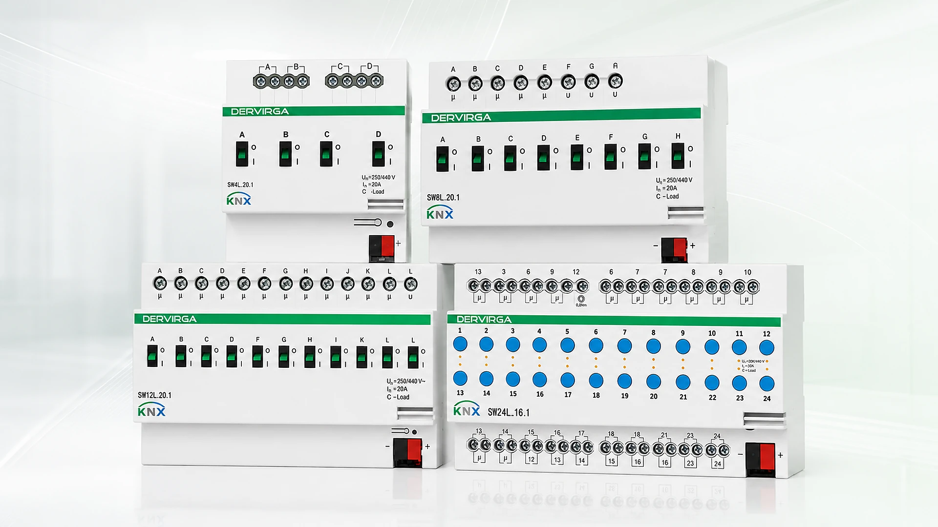
Compare four KNX switch actuator configurations according to output-channel quantity, confirmed resistive-load rating per channel, DIN rail width, manual operation and certification status.
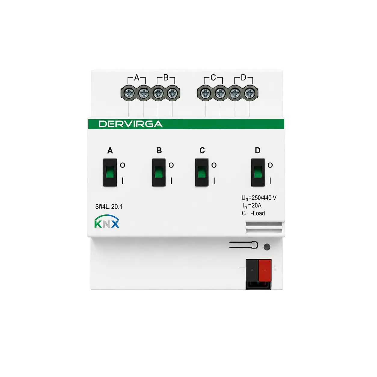
4-Channel 20A KNX Switch Actuator
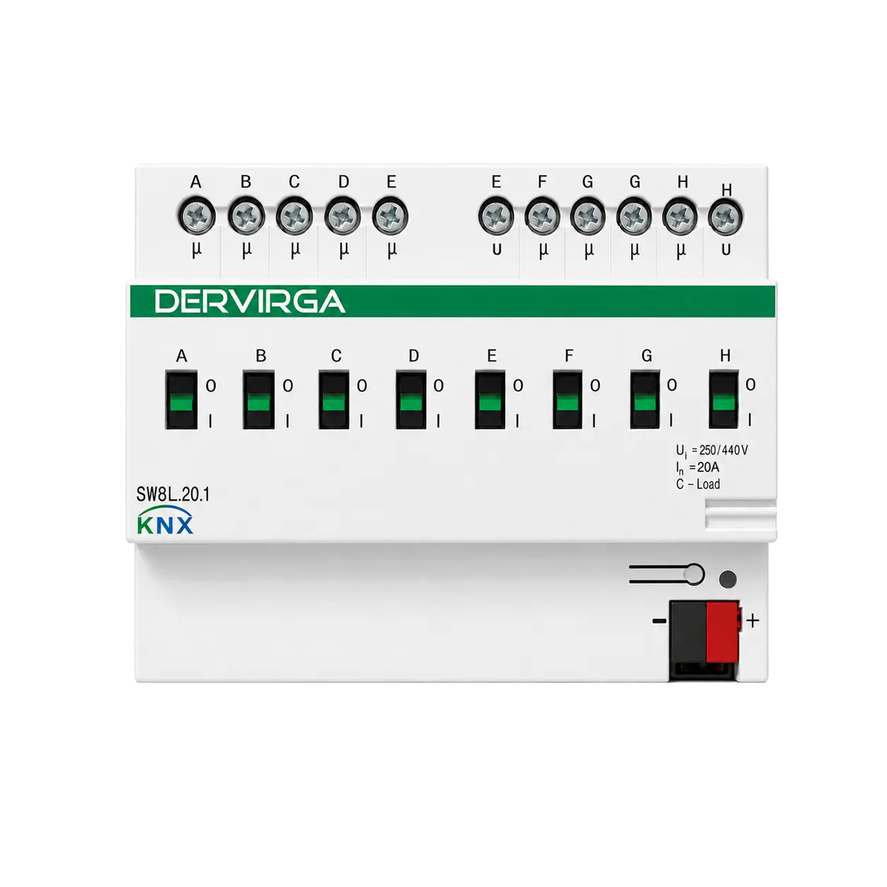
8-Channel 20A KNX Switch Actuator
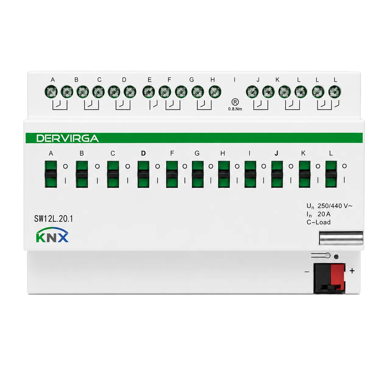
12-Channel 20A KNX Switch Actuator
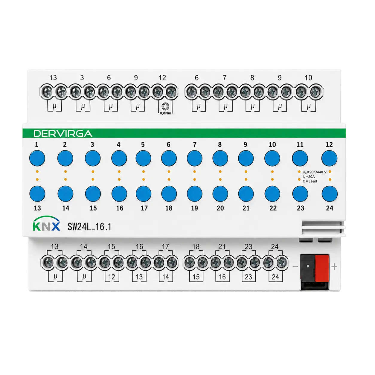
24-Channel 16A KNX Switch Actuator
Compare confirmed channel quantities, resistive-load ratings, DIN rail dimensions, manual-control methods, environmental parameters and certification status across all four SW Series KNX switch actuators.
| Technical Specification |
SW4L.20.1
4 Channels · 20A
|
SW8L.20.1
8 Channels · 20A
|
SW12L.20.1
12 Channels · 20A
|
SW24L.16.1
24 Channels · 16A
|
|---|---|---|---|---|
| Model Configuration | ||||
| Output Channels | 4 | 8 | 12 | 24 |
| Output Type | Independent Relay Outputs | Independent Relay Outputs | Independent Relay Outputs | Independent Relay Outputs |
| Resistive Load Rating per Channel | 20A | 20A | 20A | 16A |
| Manual Control | Lever-Style | Lever-Style | Lever-Style | Push Button |
| Status Indication | — | — | — | LED Indication |
| Certification | KNX Certified · CE | KNX Certified · CE | CE | CE |
| KNX & Electrical | ||||
| Communication Protocol | KNX TP | KNX TP | KNX TP | KNX TP |
| KNX Bus Voltage | 21–30V DC | 21–30V DC | 21–30V DC | 21–30V DC |
| KNX Bus Current | <12mA | <12mA | <12mA | <12mA |
| KNX Bus Power Consumption | <360mW | <360mW | <360mW | <360mW |
| Output Circuit Voltage | 230V AC, 50Hz | 230V AC, 50Hz | 230V AC, 50Hz | 230V AC, 50Hz |
| ETS Versions | ETS 5 / ETS 6 | ETS 5 / ETS 6 | ETS 5 / ETS 6 | ETS 5 / ETS 6 |
| Installation & Environment | ||||
| Installation | Standard 35mm DIN Rail | Standard 35mm DIN Rail | Standard 35mm DIN Rail | Standard 35mm DIN Rail |
| DIN Rail Module Width | 4SU | 9SU | 13SU | 13SU |
| Dimensions | 75 × 90 × 64.5 mm | 148 × 90 × 64.5 mm | 221 × 90 × 64.5 mm | 221 × 90 × 64.5 mm |
| Connection Terminals | Screw Terminals | Screw Terminals | Screw Terminals | Screw Terminals |
| Solid Conductor | 0.5–4.0mm² | 0.5–4.0mm² | 0.5–4.0mm² | 0.5–4.0mm² |
| Stranded Conductor | 0.5–2.5mm² | 0.5–2.5mm² | 0.5–2.5mm² | 0.5–2.5mm² |
| Operating Temperature | −25°C to +85°C | −25°C to +85°C | −25°C to +85°C | −25°C to +85°C |
| Storage Temperature | −20°C to +60°C | −20°C to +60°C | −20°C to +60°C | −20°C to +60°C |
| Working Humidity | 10–95% RH, non-condensing | 10–95% RH, non-condensing | 10–95% RH, non-condensing | 10–95% RH, non-condensing |
Choose this model for four independently switched circuits when a compact 4SU format and a confirmed 20A resistive-load rating per channel are required.
Choose this model for eight independently controlled 20A resistive-load outputs in a 9SU DIN rail format with KNX and CE certification.
Choose this model when twelve independently controlled outputs with a confirmed 20A resistive-load rating per channel are required in a 13SU housing.
Choose this model for 24 independently controlled 16A resistive-load outputs with push-button manual control, LED indication and a 13SU DIN rail width.
Each SW Series actuator receives switching commands through the KNX TP bus and controls independent relay outputs for confirmed 230V AC resistive-load circuits.
KNX devices or automation logic send switching telegrams through the KNX TP bus to the selected SW Series actuator.
Each output channel operates an independent relay, allowing the configured KNX function to switch its connected circuit without combining channel ratings.
The relay output switches the connected resistive-load circuit according to the confirmed per-channel rating of the selected SW Series model.
Install SW Series actuators in the KNX distribution board to provide independently controlled relay outputs for residential, hotel and commercial automation projects.
KNX wall controls, sensors or automation logic send commands through the KNX TP bus. The selected SW Series actuator then operates its independent relay outputs according to the configured ETS functions.
Organize independently controlled circuits in the apartment distribution board and select the required output quantity according to the project circuit schedule.
Use KNX commands, scenes and delay functions to coordinate independently switched circuits across guestrooms, corridors and selected shared areas.
Select 8-, 12- or 24-channel models for projects requiring a larger number of independent switching outputs within the KNX electrical distribution system.
Coordinate the actuator with the KNX power supply, wall controls, sensors and gateways while reserving the correct DIN rail width for the selected model.
Configure independent relay outputs, central commands, timing, scenes, logic, feedback and recovery behavior through ETS 5 or ETS 6 according to the requirements of the KNX project.
The SW Series supports project configuration through ETS 5 and ETS 6. Select the correct product entry for the actuator model, configure the required channel parameters and commission the device within the KNX installation.
The following functions are recorded for the SW Series. The exact parameter names and object arrangement may depend on the verified ETS database version.
Compare confirmed housing dimensions and DIN rail widths, then complete mounting, wiring and ETS commissioning according to the selected model and project documentation.
All four models use the same 90mm housing height and 64.5mm depth. Select the required panel space according to the confirmed width and DIN rail module size.
Connection format: standard 35mm DIN rail installation with screw terminals. Supported conductor sizes are 0.5–4.0mm² for solid conductors and 0.5–2.5mm² for stranded conductors. Follow the model-specific wiring diagram when completing KNX bus and output-circuit connections.
Reserve the required DIN rail space, complete the electrical connections and commission the actuator according to the selected SW Series model.
Allocate 4SU, 9SU or 13SU in the distribution board according to the selected actuator model.
Secure the actuator in the planned panel position while maintaining suitable space for wiring, identification and servicing.
Connect the KNX TP bus and independently controlled output circuits according to the model-specific wiring diagram and terminal identification.
Download the ETS configuration, verify manual control and test the configured switching, scene, timing, logic and feedback functions.
Request product data, installation and dimension information, wiring references and ETS resources for the selected SW Series KNX switch actuator.
Review model specifications, channel quantities, resistive-load ratings, dimensions, installation data and environmental parameters.
Review DIN rail mounting, terminal identification, wiring guidance, commissioning procedures and model-specific housing dimensions.
Check KNX TP bus connections, relay-output terminal arrangement and model-specific circuit wiring references.
Configure switching, timing, scenes, logic, feedback and restoration behavior for the selected SW Series actuator through ETS 5 or ETS 6.
Quick answers about model selection, current ratings, certification, manual control, ETS configuration and installation.
SW4L.20.1, SW8L.20.1 and SW12L.20.1 provide a confirmed 20A resistive-load rating per channel. SW24L.16.1 provides 24 independent outputs with a confirmed 16A resistive-load rating per channel.
No. The displayed 16A or 20A value is the confirmed resistive-load rating for each individual output channel. A total actuator current is not calculated by multiplying the channel quantity by the per-channel rating.
SW4L.20.1 and SW8L.20.1 are listed with KNX certification and CE. SW12L.20.1 and SW24L.16.1 are listed with CE.
Yes. SW4L.20.1, SW8L.20.1 and SW12L.20.1 use lever-style manual control. SW24L.16.1 uses push-button manual control and includes LED indication.
The SW Series supports configuration through ETS 5 and ETS 6. Select the product database entry corresponding to the actuator model used in the project.
SW4L.20.1 requires 4SU, SW8L.20.1 requires 9SU, and both SW12L.20.1 and SW24L.16.1 require 13SU. All models are designed for standard 35mm DIN rail installation.
Functions include independent switching, central commands, two preset values per channel, five scenes per channel, delay, staircase lighting, flashing, threshold, force, safety, status feedback, AND/OR/XOR logic and restoration behavior.
Installation, electrical wiring, inspection and KNX commissioning should be completed by qualified personnel in accordance with the project documentation and applicable local requirements.

Share your required channel quantity, resistive-load information, DIN rail arrangement and project requirements with DERVIRGA for SW4L.20.1, SW8L.20.1, SW12L.20.1 or SW24L.16.1 model selection, quotation and technical support.
Fill out the form below, and we will be in touch shortly.
Please enter the authorization code provided by DERVIRGA to download this file.