
4 / 8
Output Channels
DERVIRGA SD Series KNX Switch Actuators provide reliable DIN rail switching control for residential, hotel and commercial building automation projects with flexible channel configurations and advanced KNX functions.
The SD Series combines compact DIN rail installation, independent relay switching and practical KNX functions in two channel configurations for residential, hotel and commercial building automation projects.
SD4L.10.1 provides four output channels in a 4SU housing, while SD8L.10.1 provides eight output channels in an 8SU housing. Both models use KNX TP communication and are rated at 10A per channel for resistive loads.
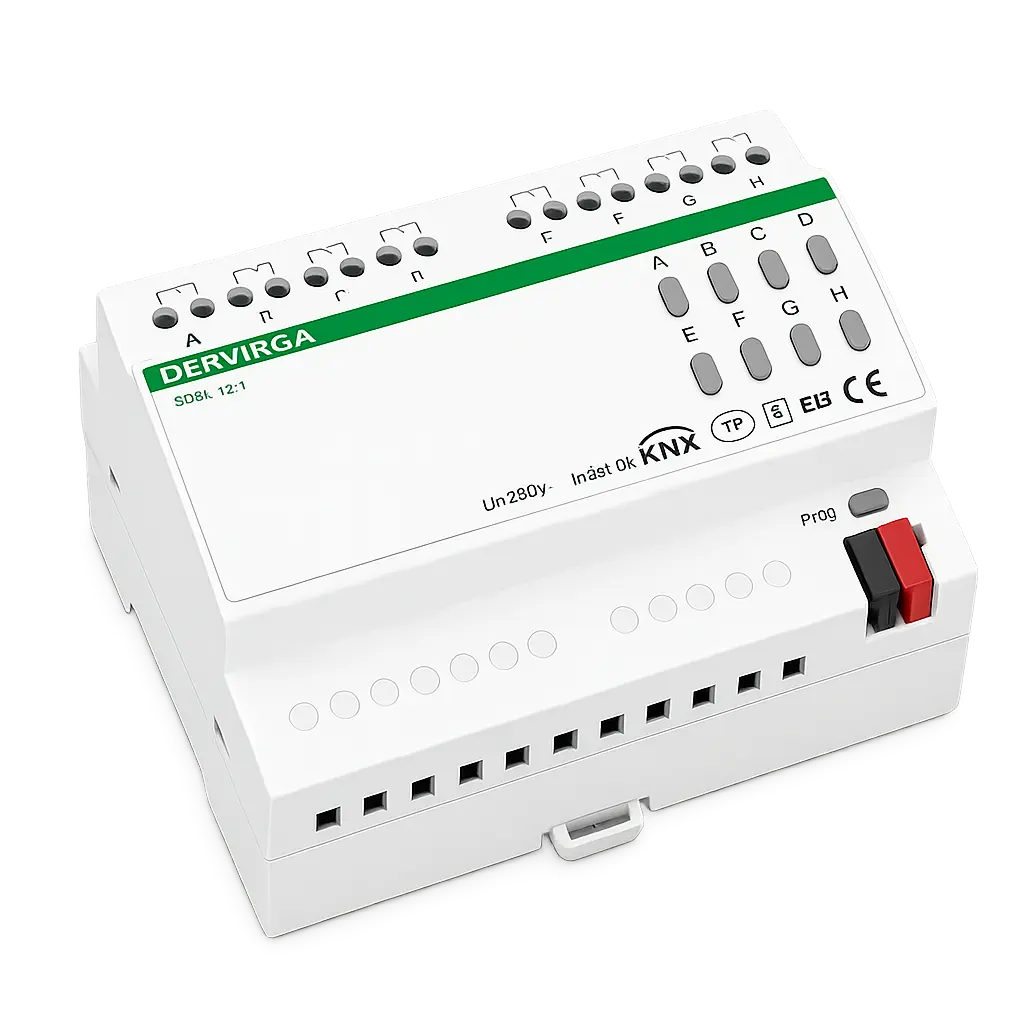
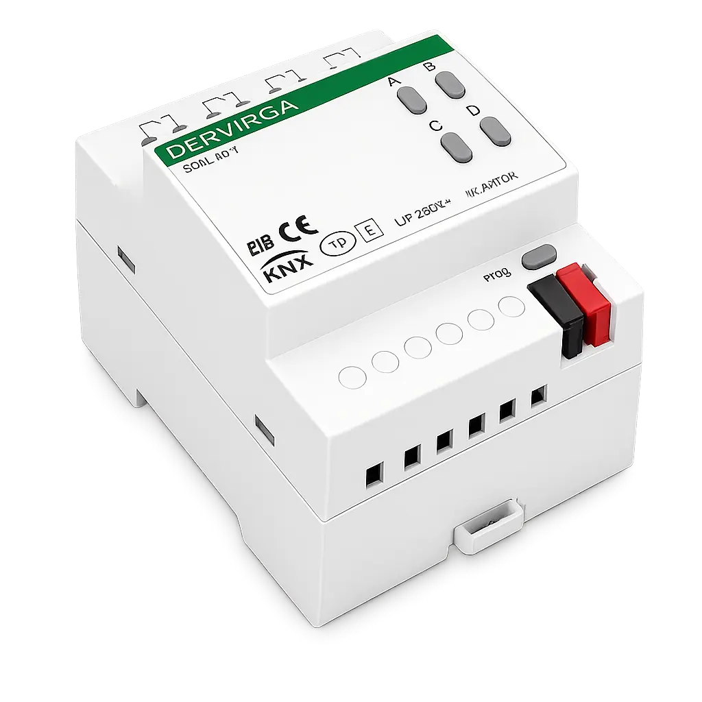
Select the four-channel or eight-channel configuration according to the number of independently controlled loads and the available DIN rail space in the distribution board.
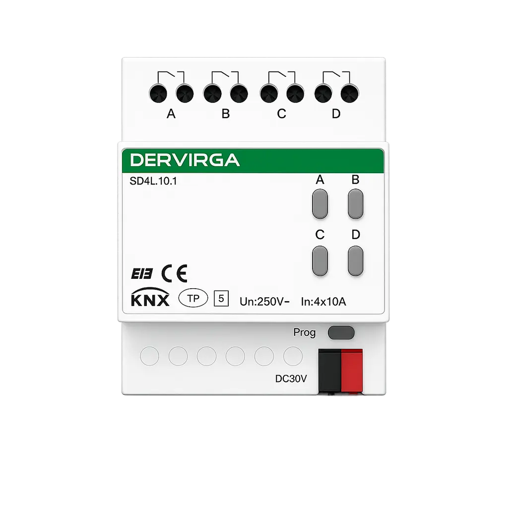
KNX 4-Channel 10A Switch Actuator
Compact four-channel configuration for projects requiring fewer independently switched circuits and a smaller DIN rail footprint.
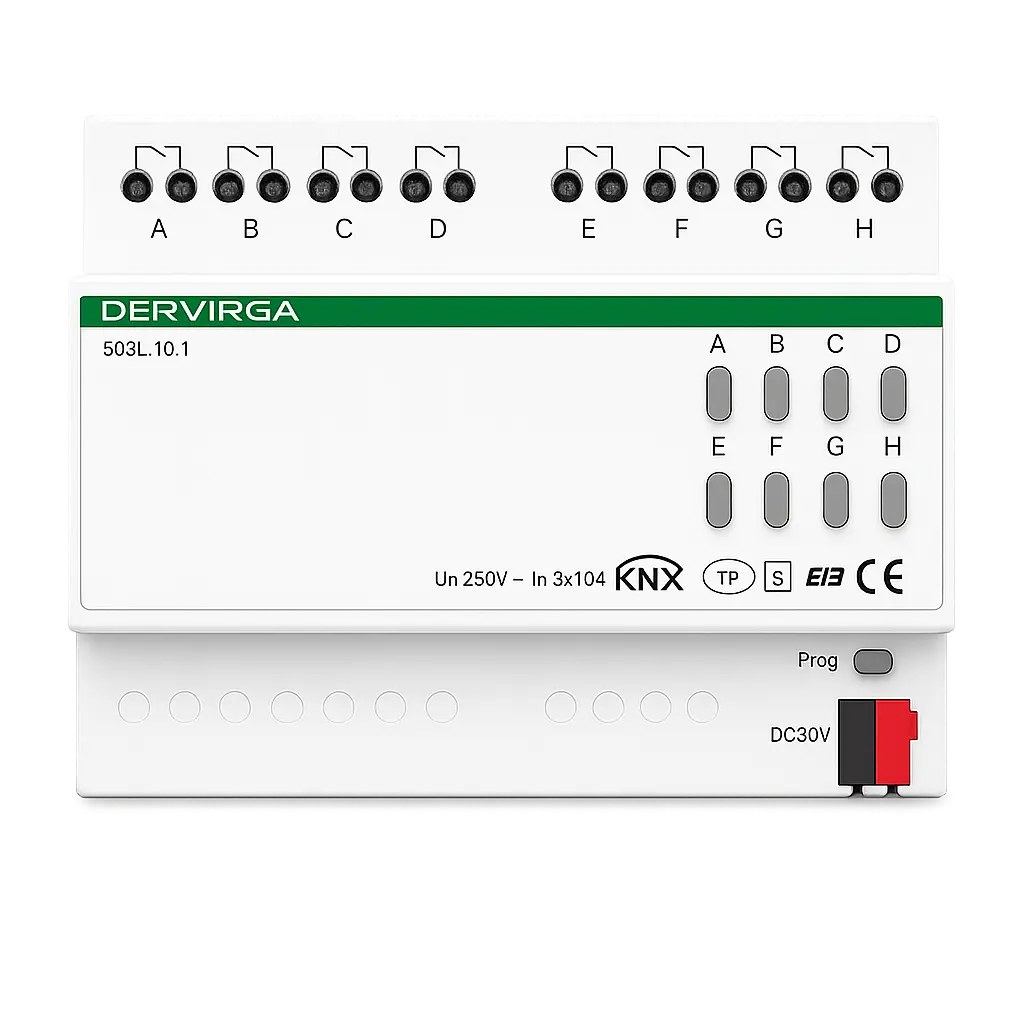
KNX 8-Channel 10A Switch Actuator
Eight-channel configuration for projects requiring more independently switched circuits within one KNX actuator.
Both models share the same KNX bus, output-current and environmental specifications. Select the required model according to output-channel quantity, total actuator current and available DIN rail space.
| Technical Specification |
SD4L.10.1
4 Channel |
SD8L.10.1
8 Channel |
|---|---|---|
| Output Configuration | ||
| Output Channels | 4 | 8 |
| Output Type | Independent Relay Outputs | Independent Relay Outputs |
| Rated Load Current | 10A per Channel | 10A per Channel |
| Load Type | Resistive Load | Resistive Load |
| Maximum Total Actuator Current | 40A | 80A |
| Rated Output Voltage | 230VAC @ 50Hz | 230VAC @ 50Hz |
| KNX Bus and Local Operation | ||
| Protocol | KNX TP | KNX TP |
| KNX Bus Voltage | 21–30VDC | 21–30VDC |
| Bus Current | <5mA | <5mA |
| Bus Power Consumption | <150mW | <150mW |
| Programming Button | Physical Address Programming | Physical Address Programming |
| Manual Buttons / Indicators | Manual Control and LED Indication | Manual Control and LED Indication |
| Installation and Environment | ||
| Installation | Standard 35mm DIN Rail | Standard 35mm DIN Rail |
| DIN Module Width | 4SU | 8SU |
| Dimensions | 72 × 90 × 64.3mm | 144 × 90 × 64.3mm |
| Operating Temperature | −5°C to +45°C | −5°C to +45°C |
| Storage Temperature | −20°C to +60°C | −20°C to +60°C |
Suitable when the project requires up to four independently switched circuits or when the available distribution-board space is limited to a 4SU actuator width.
Suitable when the project requires five to eight independently switched circuits and an 8SU actuator can be accommodated in the distribution board.
The SD Series converts KNX bus commands into independent 230VAC relay outputs, providing four-channel or eight-channel switching with a confirmed 10A resistive-load rating for every output.
Switching commands and device configuration are delivered through the KNX twisted-pair bus.
Four or eight independent relay channels convert KNX commands into controlled switching actions.
Each output provides relay-based on/off switching for suitable project circuits within the confirmed electrical rating.
The SD Series is designed for centralized DIN rail switching where four or eight independent relay outputs are required within residential, hotel and commercial KNX distribution systems.
Install the SD actuator on a standard 35mm DIN rail to receive KNX TP commands and control independently assigned relay circuits from one distribution board.
Independent switching of room lighting and suitable service circuits within a KNX guest-room control design.
Centralized relay control for independently assigned room, floor and common-area circuits in a KNX villa project.
Grouped switching for suitable office, corridor and shared-area circuits installed within KNX distribution panels.
Compact four- or eight-channel actuator selection for centralized switching within new or upgraded KNX panels.
Configure independent switching channels, timing behavior, scenes, logic and feedback functions through ETS 5 or ETS 6 according to the control requirements of each KNX project.
SD4L.10.1 and SD8L.10.1 are configured as part of the same SD Series product range, with model-specific channel quantities selected during project engineering.
Add the SD Series ETS product database to the KNX project workspace.
Assign channel behavior, timing, scenes, logic and feedback parameters.
Program the physical address and transfer the completed application configuration.
Select and combine the required functions according to circuit use, control sequence and project-level KNX logic.
Both SD Series models share the same 90mm height and 64.3mm depth. Select the required four- or eight-channel actuator according to the available DIN rail width and project circuit quantity.
SD4L.10.1 occupies a 4SU DIN rail width, while SD8L.10.1 provides twice the output quantity in an 8SU housing.
Common mounting format: Both models are designed for standard 35mm DIN rail installation inside a suitable electrical distribution enclosure.
Complete mechanical installation and electrical wiring before assigning the physical address and downloading the final ETS configuration.
Disconnect the relevant supply circuits and verify that the installation is de-energized before beginning work.
Position the actuator on the standard 35mm DIN rail and secure it inside the distribution enclosure.
Connect the KNX bus and relay-output circuits according to the approved project wiring diagram and product documentation.
Assign the physical address, download the channel configuration and test manual and KNX-controlled operation.
Download the shared technical documents for SD4L.10.1 and SD8L.10.1, or contact our team for model selection, wiring and KNX commissioning support.
Series specifications, electrical ratings, dimensions, channel configurations and KNX product information.
DIN rail mounting, terminal connection, programming-button operation and commissioning instructions.
Reference diagram for KNX bus connection, relay channels, load circuits and distribution-board wiring.
Import package for SD Series project configuration, physical-address programming and KNX channel commissioning.
Share your channel quantity, load information and KNX project requirements with our team for technical review.

Share your circuit quantity, load information and project requirements with DERVIRGA for SD4L.10.1 or SD8L.10.1 model selection, quotation and technical support.
Fill out the form below, and we will be in touch shortly.
Please enter the authorization code provided by DERVIRGA to download this file.