
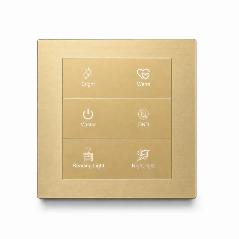
K602 KNX Metal Smart Switch Panel Series
The K602 Series is a wall-mounted KNX metal smart switch panel designed for lighting, scene and local relay control. Its metal panel is fully CNC-machined to a tolerance of ±0.05 mm, with configurable button layouts, integrated relay-output versions and project-selectable surface finishes. KNX TP communication and a 12–30 V DC auxiliary supply support professional hotel, villa, apartment and commercial building projects.
KNX Control Built for Professional Projects
The K602 Series combines KNX TP communication, lighting and scene commands, integrated relay-output versions and full-CNC metal construction for hotel, residential and commercial control applications.
KNX TP Communication
Connect the panel to a KNX TP system for coordinated wall control within professional building-automation projects.
Lighting Control
Send KNX switching commands for room lighting functions from a dedicated wall-mounted control point.
Scene Control
Trigger programmed room scenes and coordinated control commands through the KNX system.
Integrated Relay Outputs
Select K602 relay-output versions with up to four 16 A outputs for local switching requirements.
Full-CNC Metal Panel
The metal panel is fully CNC-machined to a recorded tolerance of ±0.05 mm for a precise project finish.
Finish & Marking Customization
Choose project-selectable surface processes, black-key options, icons, characters and logo customization.
Engineering Specifications for K602 Project Selection
Review the confirmed construction, electrical and environmental data for K602 project planning, configuration selection and quotation preparation.
Product Construction & Configuration
| Communication Protocol | KNX TP |
|---|---|
| System Interface | KNX / EIB bus |
| Product Type | Wall-mounted KNX metal switch panel |
| Button Configurations | 1–6 button layouts |
| Panel Construction | Metal panel |
| Machining | Full-CNC machining, ±0.05 mm |
| Surface Processes | Brushed and anodized; sandblasted and anodized; electroplated |
| Button Option | Black buttons available |
| Customization | Icons, characters, logo and surface finish |
| Installation | Wall mounted |
Electrical, Relay & Environmental
| KNX Bus Voltage | 20–30 V DC |
|---|---|
| KNX Bus Current | 10 mA at 30 V |
| KNX Power Consumption | 0.3 W |
| Auxiliary Supply | 12–30 V DC |
| Auxiliary Current | 25 / 40 / 52 mA at 30 V, depending on configuration |
| Auxiliary Power | 0.73 / 1.16 / 1.56 W, depending on configuration |
| Relay Output Range | 1–4 outputs, depending on configuration |
| Rated Relay Load | 16 A per output |
| Control Functions | Lighting switching, scene control and local relay control |
| Operating Temperature | −10°C to +65°C |
| Ambient Humidity | 5%–95% RH, non-condensing |
Button layout, relay-output version, auxiliary power requirements and project finish should be confirmed together during product selection. Contact DERVIRGA for configuration guidance, installation information and project-specific technical documentation.
Visible Panel Layouts for K602 Project Selection
The layouts shown below illustrate K602 panel-face arrangements for project discussion. Relay-output version, KNX function assignment and final ordering configuration are confirmed together during product selection.
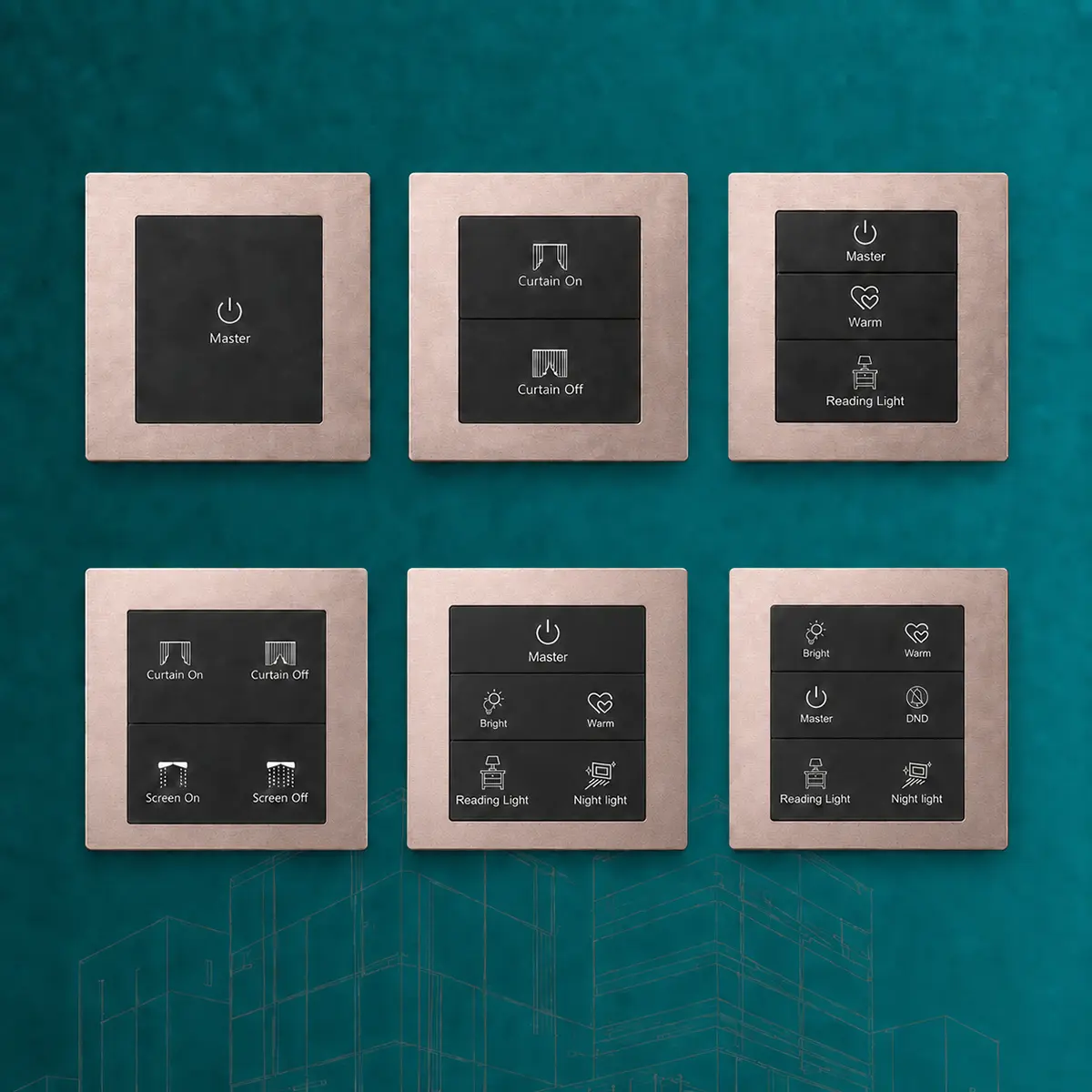
Layout 01
Single Full-Size Surface
A single large control surface shown for a focused KNX room-command assignment.
Layout 02
Two Stacked Surfaces
Two vertically arranged control surfaces for two project-assigned KNX commands.
Layout 03
Three Stacked Surfaces
Three vertically arranged surfaces for a broader set of room-control commands.
Layout 04
Four-Surface Grid
A 2 × 2 face arrangement for grouped room functions and scene assignments.
Layout 05
Five-Surface Arrangement
One full-width upper surface combined with four lower control surfaces.
Layout 06
Six-Surface Grid
A 2 × 3 face arrangement for expanded project-specific KNX command assignment.
Metal Construction and Project-Selectable Finishes
Configure the K602 Series with full-CNC metal construction, project-selectable surface processes, black-button options and customized icons, characters or logos for coordinated KNX project applications.
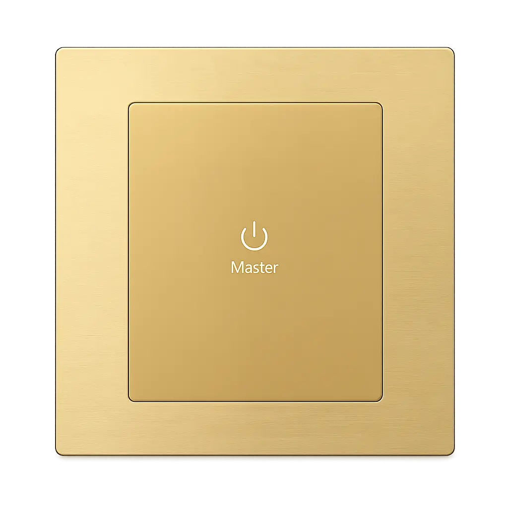
Full-CNC Metal Panel
The K602 metal panel is fully CNC-machined to a recorded tolerance of ±0.05 mm for precise panel geometry and a consistent project finish.
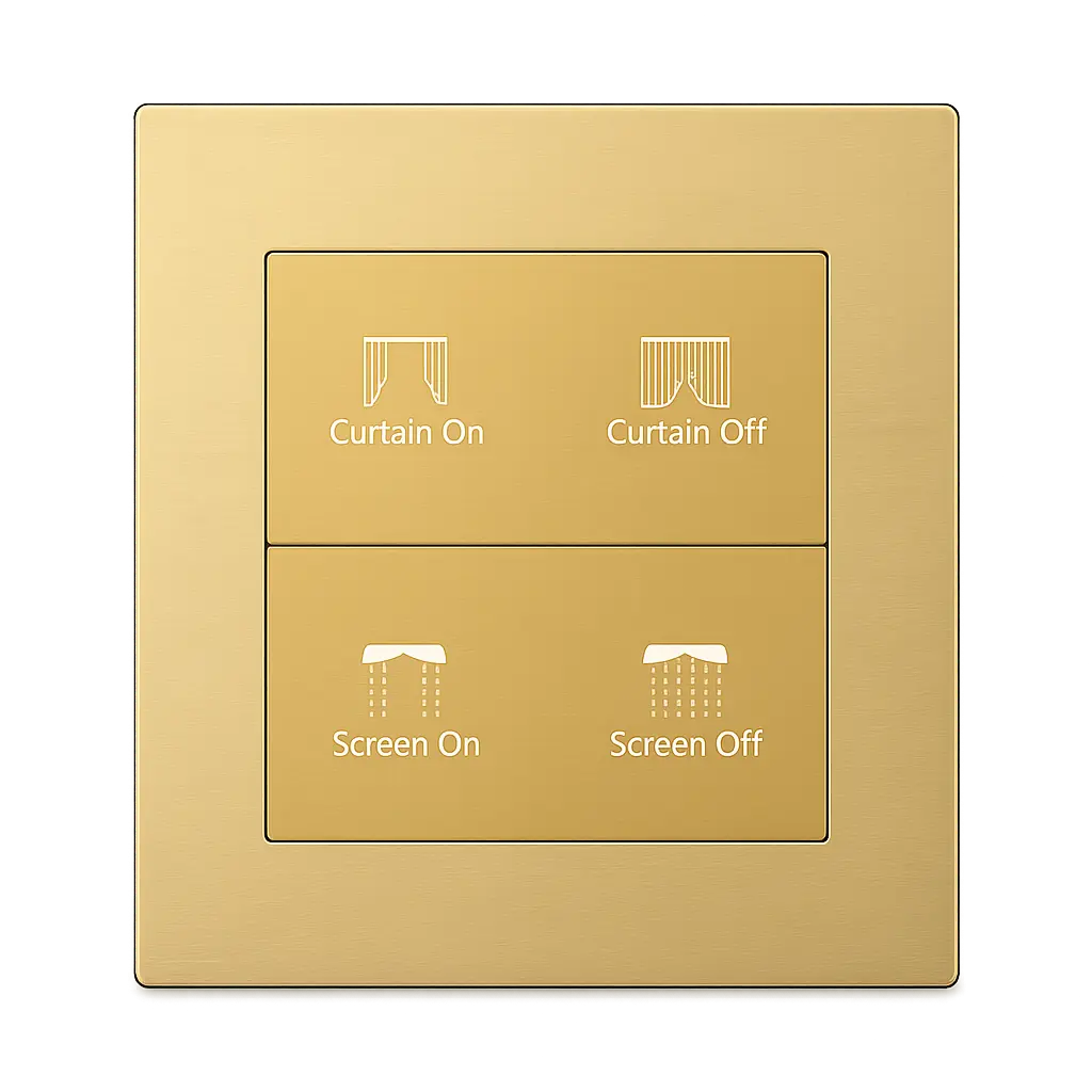
Project-Selectable Surface Processes
Available process records include brushed and anodized, sandblasted and anodized, and electroplated surface treatments. Final appearance is confirmed during product selection.
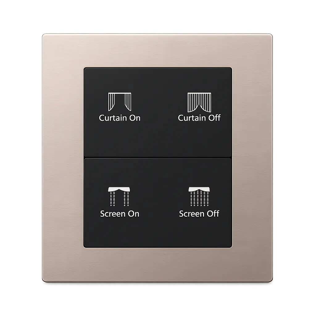
Black Button Option
Black buttons are recorded as an available option for selected K602 configurations, providing a contrasting appearance with the surrounding metal frame.
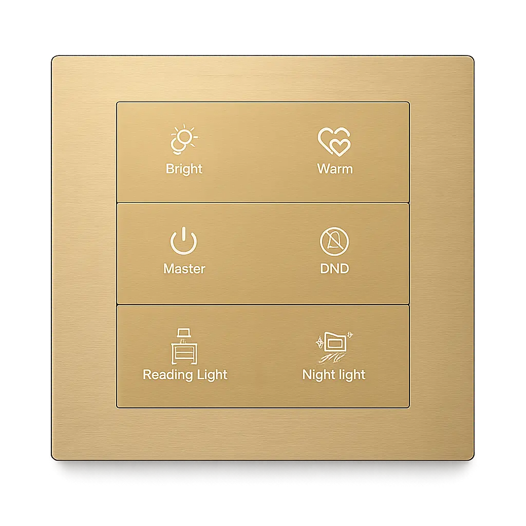
Icons, Characters & Logo
Icons, function characters, logo marking and surface-finish details can be coordinated for OEM/ODM and project-specific panel requirements.
K602 Control Panels for Coordinated Interior Projects
Use the K602 Series as part of coordinated wall-control arrangements for hotel, residential and commercial interiors. Final device combinations, control functions and surface finishes are selected for each project.
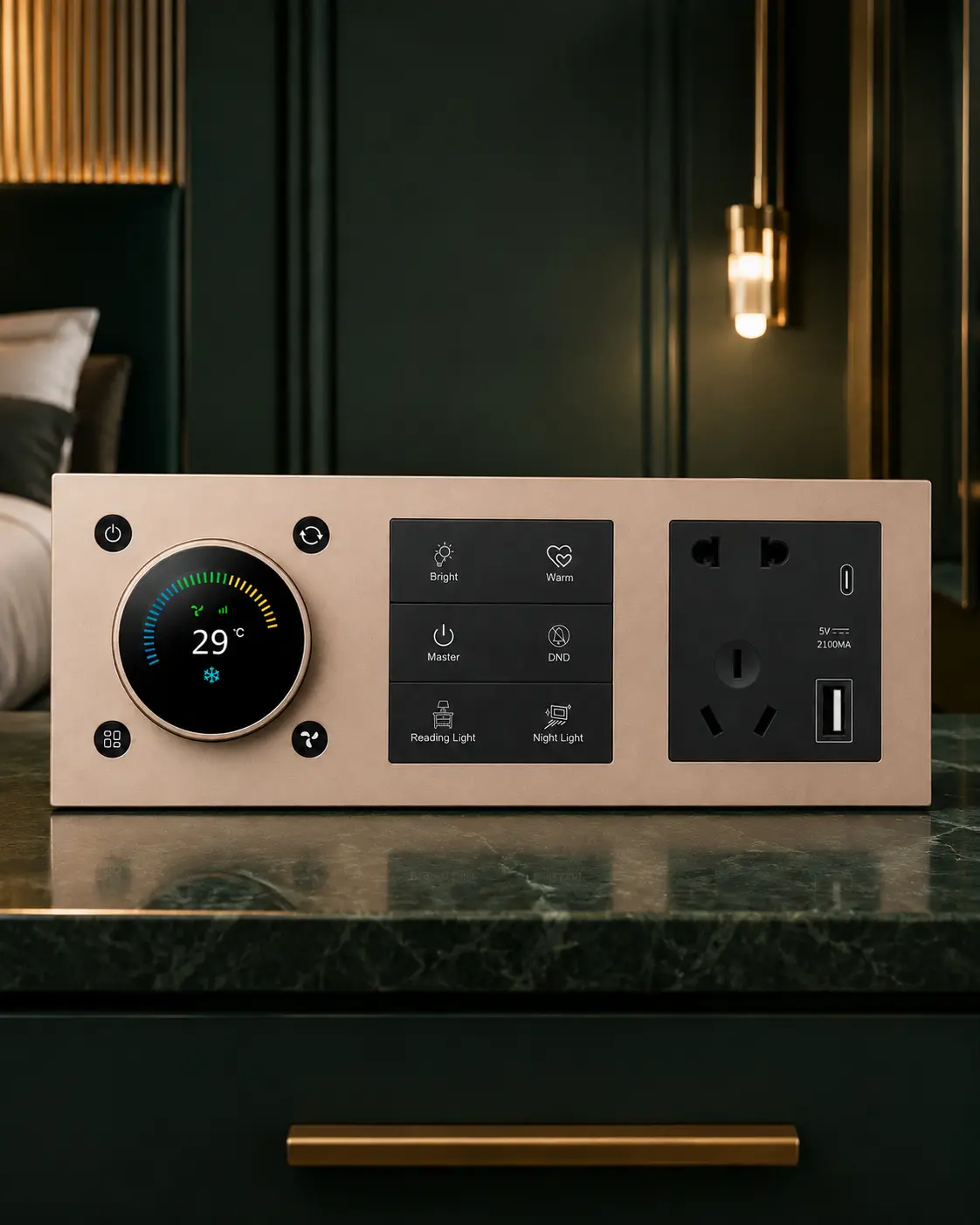
Hotel Guest Rooms
Coordinate K602 wall control with matching room-control and socket modules for guest-room applications requiring a unified metal-panel appearance.
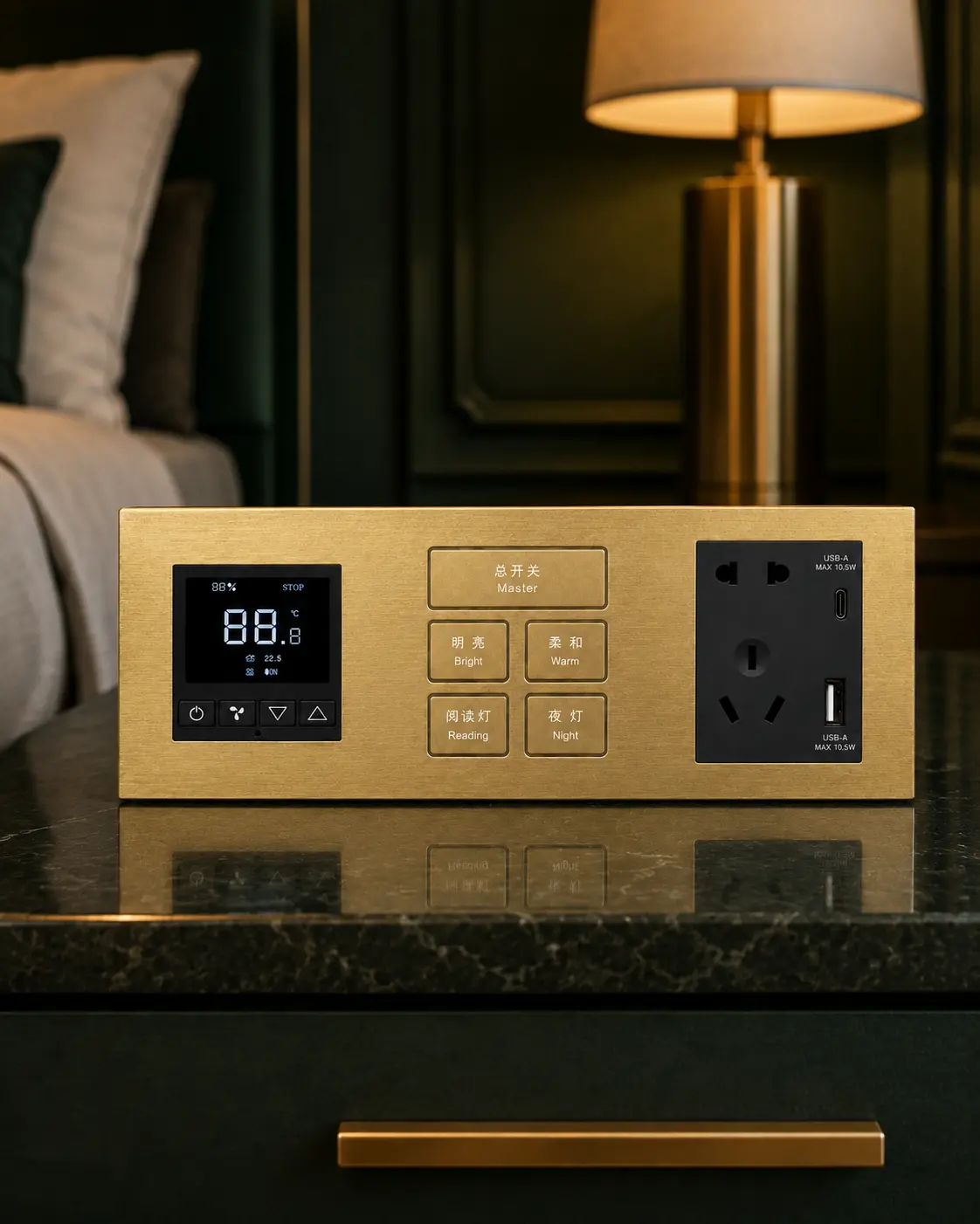
Apartments & Villas
Combine K602 with coordinated control and power modules for apartments and villas where wall functions and interior finishes are selected together.
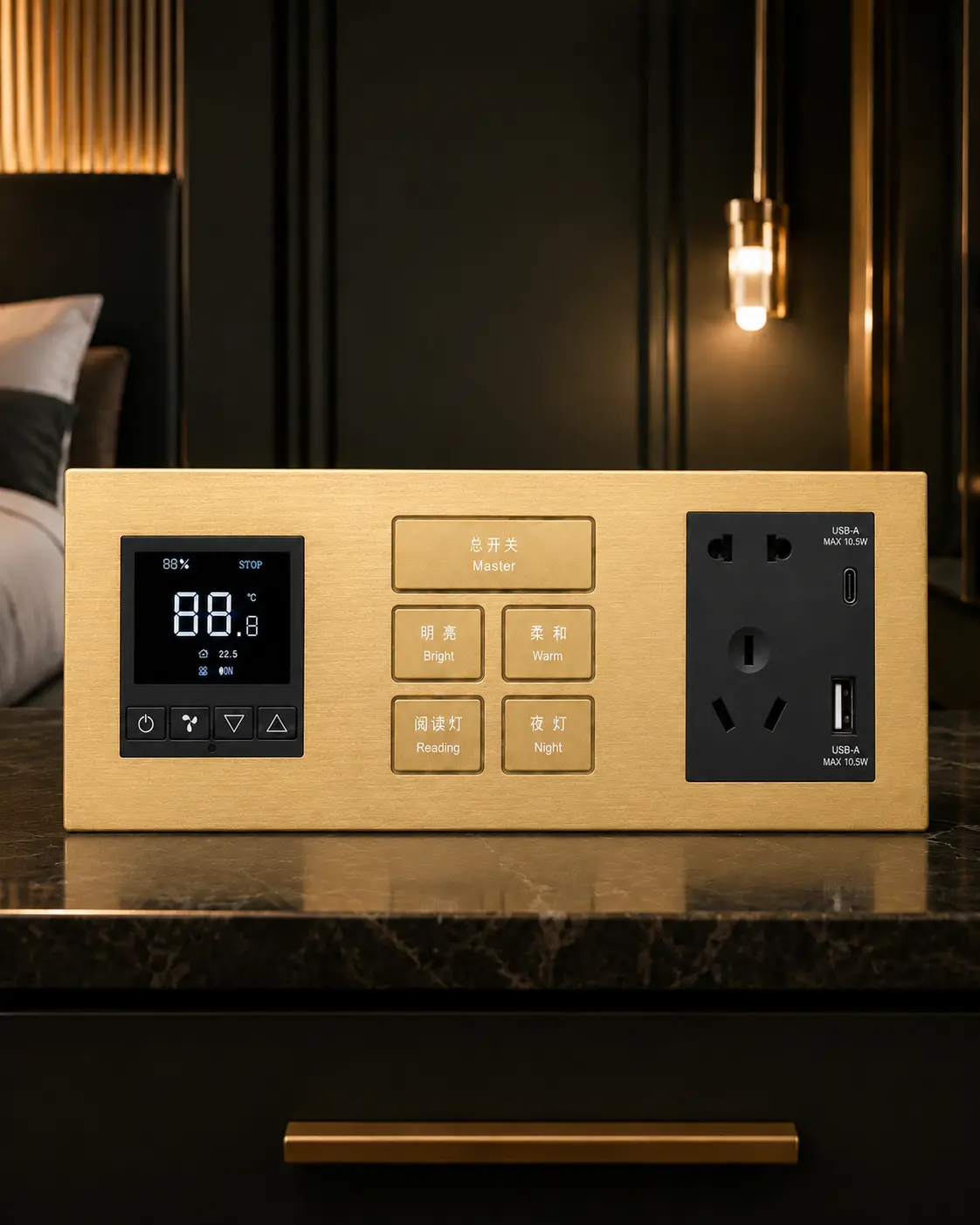
Matching Panel Combinations
Build consistent multi-module wall arrangements using aligned metal frames, KNX controls, room controllers and socket modules.
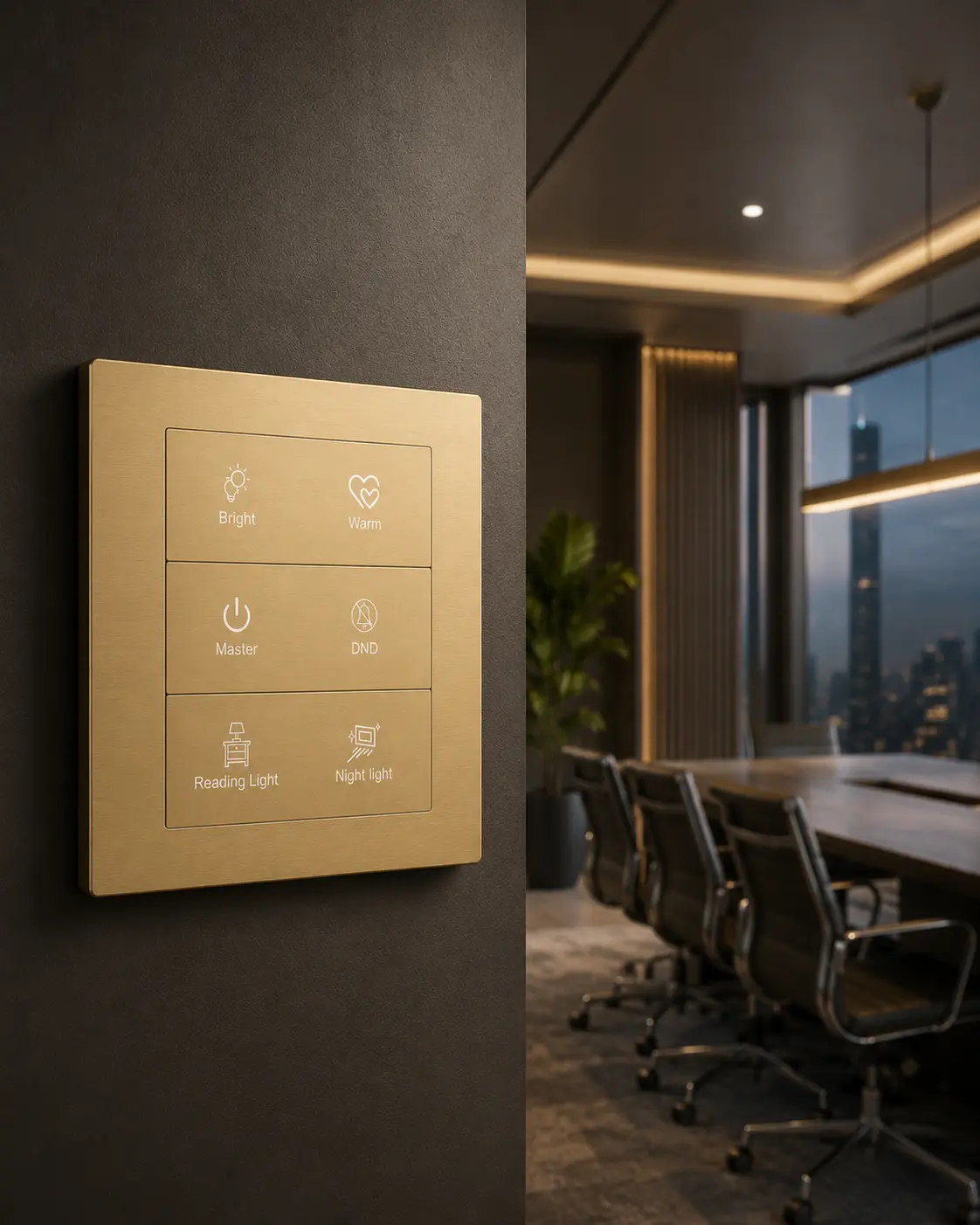
Commercial Interiors
Use configurable K602 control surfaces for project-assigned lighting and scene commands in meeting rooms, offices and commercial spaces.
KNX Power, Relay Versions and System Integration
Plan the K602 Series with KNX TP communication, a separate 12–30 V DC auxiliary supply and project-selected relay-output versions. Final configuration values should be confirmed together during product selection.
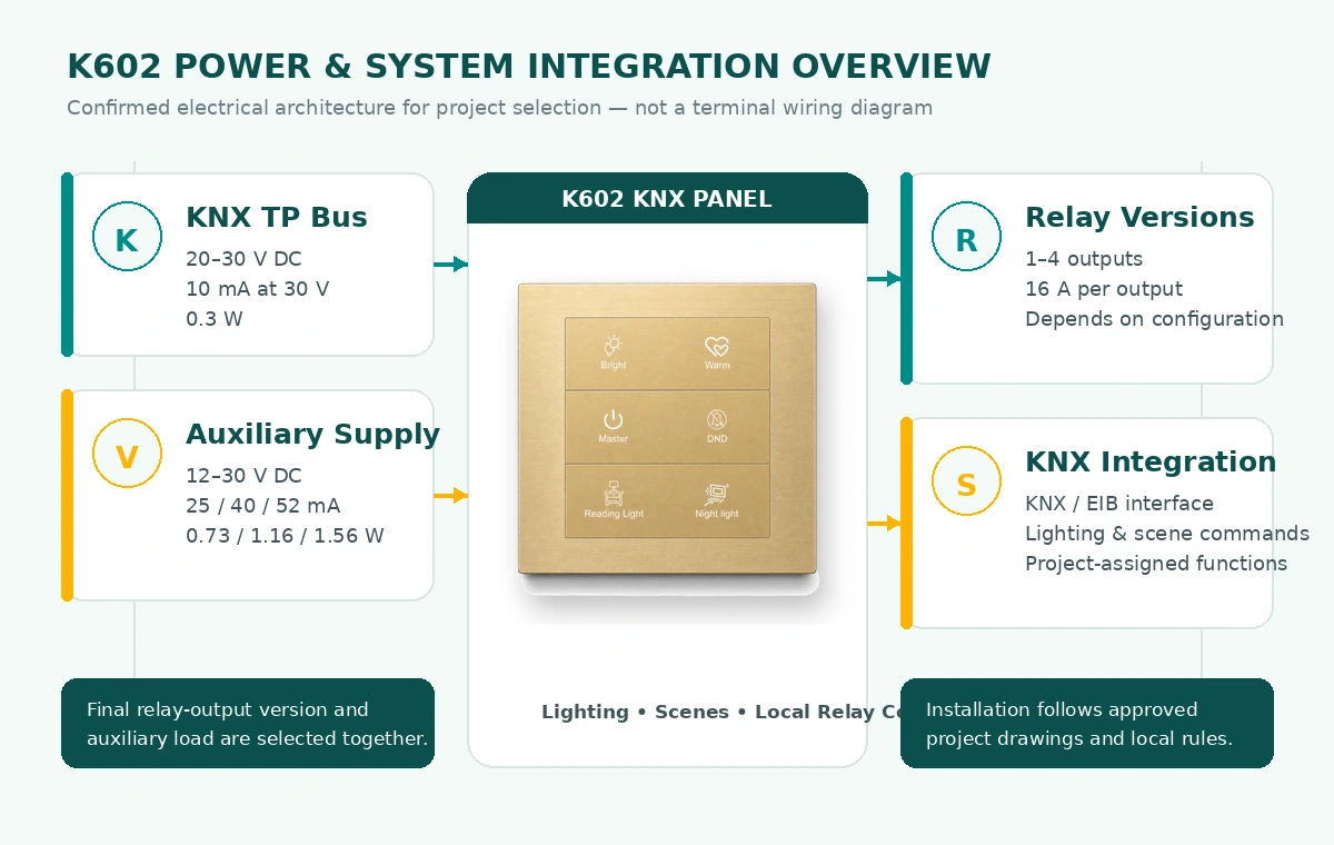
| Communication Protocol | KNX TP |
|---|---|
| System Interface | KNX / EIB bus |
| KNX Bus Voltage | 20–30 V DC |
| KNX Bus Current | 10 mA at 30 V |
| KNX Power Consumption | 0.3 W |
| Relay Output Range | 1–4 outputs, depending on configuration |
| Rated Relay Load | 16 A per output |
Confirm the button layout, relay-output version and auxiliary-power requirement together before ordering. Installation should be completed by qualified professionals in accordance with approved project drawings and local electrical regulations.
Standard Dimensions for K602 Project Installation
The K602 Series uses a confirmed 86 × 86 mm panel format with a 7 mm front-panel thickness and a 35 mm rear-housing depth. Use the approved project drawing to confirm the mounting arrangement, cable routing and installation clearances before site work.
Product Dimensions
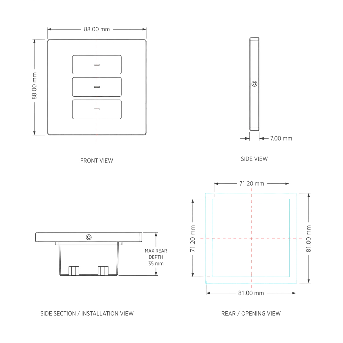
Panel Size
Panel Thickness
Rear Housing Depth
Installation Process
Verify the panel position, mounting arrangement, mechanical clearances and ordered K602 configuration against the approved project drawing.
Isolate the electrical supply and route the KNX TP bus and 12–30 V DC auxiliary supply according to the approved electrical design.
Complete the model-specific KNX, auxiliary-power and relay-output connections, arrange the wiring correctly and secure the rear housing.
Fit the metal front panel, complete KNX commissioning and verify all project-assigned button, scene and relay functions before handover.
Installation, wiring and KNX commissioning must be completed by qualified professionals. Confirm the ordered K602 version, mounting arrangement, wiring space and relay-output configuration before installation.
Request K602 Documentation and Project Support
Submit a project request for current K602 specifications, installation information, wiring guidance and KNX integration support. The response is matched to the confirmed panel layout, relay-output version, finish and project requirements.
Need K602 Technical Assistance?
Share the project type, required K602 configuration and integration requirements. DERVIRGA will help confirm the suitable panel layout, relay-output version, finish, power requirements and supporting technical information.
Button layout, relay-output version and finish selection
KNX TP, auxiliary-power and system-integration support
OEM/ODM markings, samples and project-document coordination
Please include the required button layout, sensor requirement, relay-output requirement, color, surface finish, project quantity, destination market and whether you need a quotation, sample or technical documentation.
Documentation Requests
Request K602 electrical data, confirmed dimensions, material options, surface finishes and configuration information for project review.
Request mounting guidance, installation precautions and the approved mechanical reference for the selected K602 version.
Request model-specific KNX TP, auxiliary-power and relay-output connection information for the ordered configuration.
Request support for KNX integration, function assignment and commissioning requirements for the project.
Configure the K602 Series for Your Project and Brand
Coordinate the K602 Series with project-selectable surface processes, panel appearance, black-button options, customized icons or branding and the required relay-output version before production.
Surface Process & Appearance
Review brushed and anodized, sandblasted and anodized, or electroplated surface processes and confirm the required project appearance before production.
Panel Layout & Function Marking
Select the visible panel layout and coordinate project-assigned icons, characters and function labels with the approved control schedule.
Black Buttons & Branding
Confirm black-button requirements together with customized logo marking, project characters and coordinated panel details for OEM/ODM applications.
Relay Version & Project Package
Confirm the required relay-output version, KNX function assignment, sample needs, packaging details and available project documentation.
Build Your K602 Configuration
Share your KNX project requirements with DERVIRGA. Our team will help coordinate the suitable K602 panel layout, relay-output version, surface process, button appearance, markings, quantity and supporting project information.
Confirm the panel layout and project-assigned control functions
Select the surface process, color, black-button option, icons and branding
Review the relay-output requirement, samples, quantity and project documents
Please include the required panel layout, sensor requirement, relay-output requirement, color, surface finish, icons or logo, project quantity, destination market and whether you need a quotation or sample.