
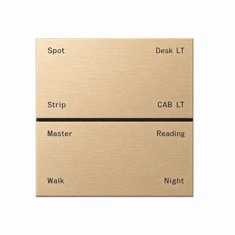
K901 KNX Metal Smart Switch Panel Series
The K901 Series is a wall-mounted KNX metal smart switch panel offered in 6- and 8-button layouts. Confirmed configurations use KNX TP communication, a 12–30 V DC auxiliary supply and four 16 A relay outputs for lighting, scene and local relay control. Brushed, sandblasted or electroplated surface options support hotel, villa, apartment and commercial building projects.
Core K901 Features for Professional KNX Projects
The K901 Series is available in 4-, 6- and 8-button layouts and combines KNX TP communication, integrated relay outputs, a built-in motion sensor and selectable metal finishes for hotel, villa, apartment and commercial building control.
KNX TP Communication
Connect the K901 panel to a KNX TP system through the 20–30 V DC bus for coordinated building-control commands.
Lighting & Scene Control
Use K901 buttons for KNX lighting switching and programmed scene commands within the project configuration.
4 × 16 A Relay Outputs
K901 product data records four integrated 16 A relay outputs for project-specific local switching requirements.
Built-In Motion Sensor
K901 product data includes a built-in motion sensor for coordinated room-control applications.
4, 6 & 8 Button Layouts
Select a 4-, 6- or 8-button front layout according to the required number of control positions.
Metal Panel & Finish Options
Choose brushed anodized, sandblasted anodized or electroplated surface treatments to coordinate the metal panel with project interiors.
Confirmed K901 Specifications for Project Selection
Review the confirmed construction, relay, power and environmental data for K901 project selection, system coordination and quotation preparation.
Product Construction & Configuration
| Communication Protocol | KNX TP |
|---|---|
| System Interface | KNX / EIB bus |
| Product Type | Wall-mounted KNX metal switch panel |
| Button Configurations | 4-, 6- and 8-button layouts |
| Panel Construction | Metal panel |
| Motion Detection | Built-in motion sensor |
| Relay Outputs | 4 integrated relay outputs |
| Rated Relay Load | 16 A per output |
| Surface Processes | Brushed and anodized; sandblasted and anodized; electroplated |
| Installation | Wall mounted |
Electrical & Environmental Specifications
| KNX Bus Voltage | 20–30 V DC |
|---|---|
| KNX Bus Current | 10 mA at 30 V |
| KNX Bus Power | 0.3 W |
| Auxiliary Supply | 12–30 V DC |
| 6-Button Auxiliary Current | 25 mA at 30 V |
| 6-Button Auxiliary Power | 0.75 W operating and standby |
| 8-Button Auxiliary Current | 52 mA at 30 V |
| 8-Button Auxiliary Power | 1.56 W operating and standby |
| Operating Temperature | −10°C to +65°C |
| Operating Humidity | 5–95% RH, non-condensing |
Auxiliary current and power vary by button configuration. The table lists the currently confirmed electrical values for the 6- and 8-button versions; specify the required 4-, 6- or 8-button layout when requesting final project details.
4-, 6- and 8-Button Layouts for K901 Project Selection
The K901 Series is available in confirmed 4-, 6- and 8-button layouts. Each configuration provides a different number of visible control positions while retaining the confirmed four integrated 16 A relay outputs.
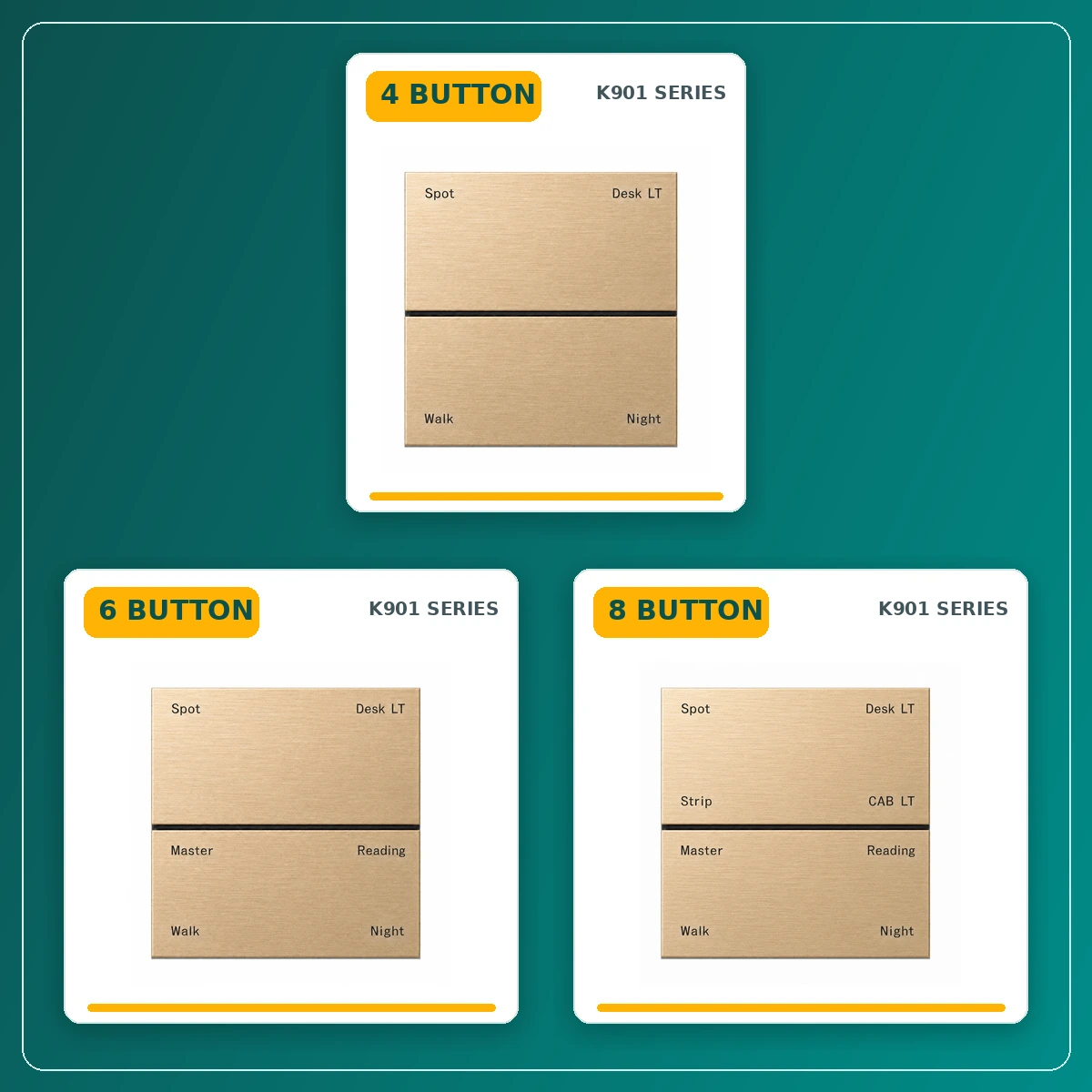
4-Button Layout
4-button configuration
A compact face layout for projects requiring selected lighting, scene and local relay control positions.
6-Button Layout
6-button configuration
Provides additional visible control positions for a broader mix of lighting, scene and local relay assignments.
8-Button Layout
8-button configuration
The largest confirmed K901 layout, providing more visible room-control positions within the same metal-panel design.
Metal Finishes and Project Customization
Configure the K901 Series with confirmed metal-panel construction, brushed anodized, sandblasted anodized and electroplated surface processes. Project-selected colors, function markings and OEM/ODM details are coordinated against approved artwork and finish samples.
Metal Panel Construction
The K901 Series uses a confirmed metal panel construction, providing a coordinated architectural control surface for KNX room-control applications.
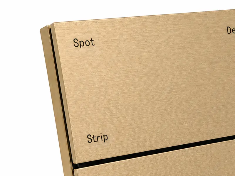
Brushed Gold Sample Finish
The supplied K901 product images show a brushed-gold finish sample. Final project color, texture and production finish are confirmed against the approved sample.
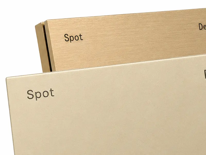
Project-Selectable Surface Processes
Recorded process options include brushed anodized, sandblasted anodized and electroplated surface treatments. Availability and final appearance are confirmed for each project order.
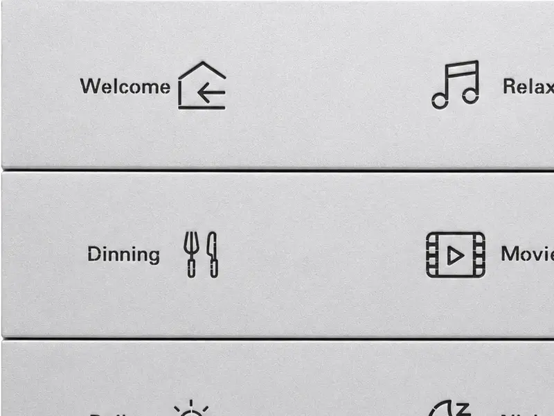
Icons, Text & OEM/ODM Branding
Brand marking, function icons, text labels, surface-finish details and packaging can be coordinated for OEM/ODM projects, subject to artwork, sample and order approval.
K901 Control for Hospitality, Residential and Commercial Projects
The K901 Series combines KNX TP communication, 4-, 6- and 8-button layouts, four integrated 16 A relay outputs and project-selectable metal finishes for coordinated control across hotel, villa, apartment and commercial building projects.
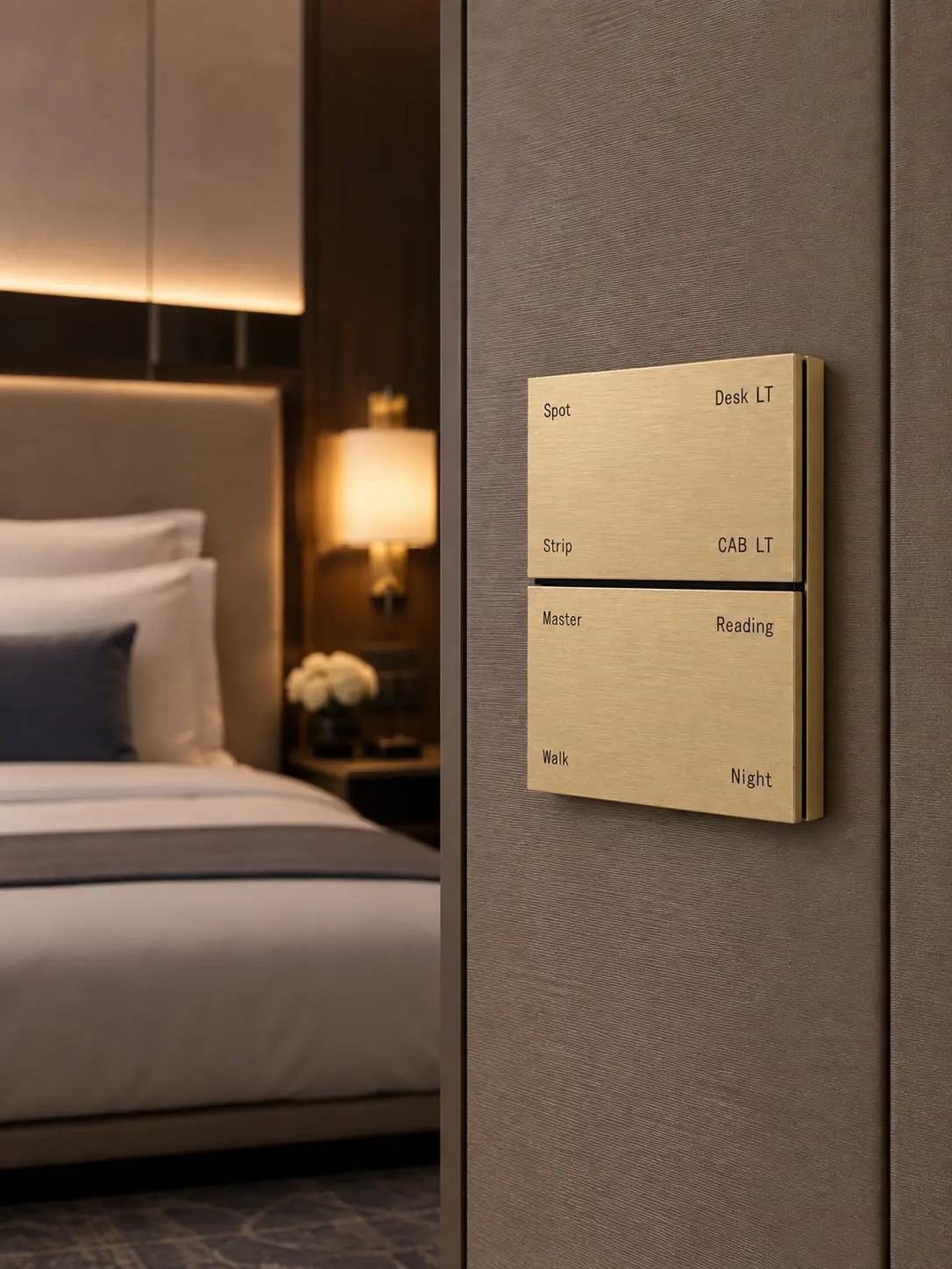
Smart Hotels
Use K901 panels for coordinated guest-room lighting, scene selection and local relay control, with button layouts and metal finishes selected to match the hotel interior.
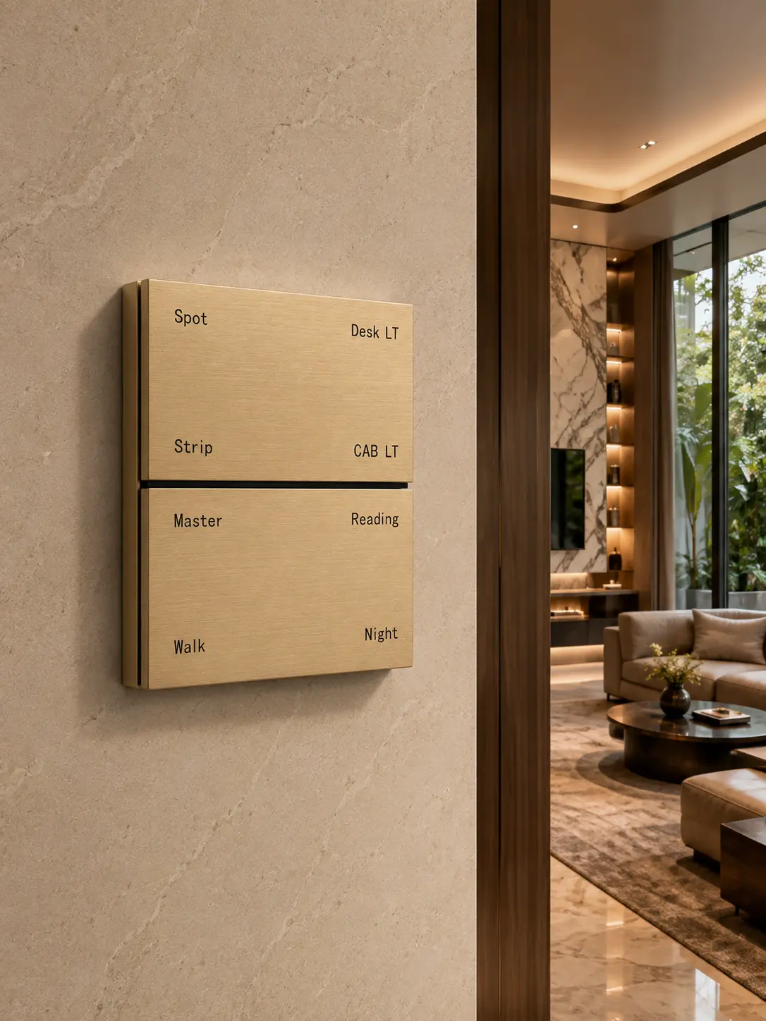
Luxury Villas
Provide personalized lighting scenes and clearly assigned wall-control functions for villas, supported by 4-, 6- and 8-button layouts and project-selected finishes.
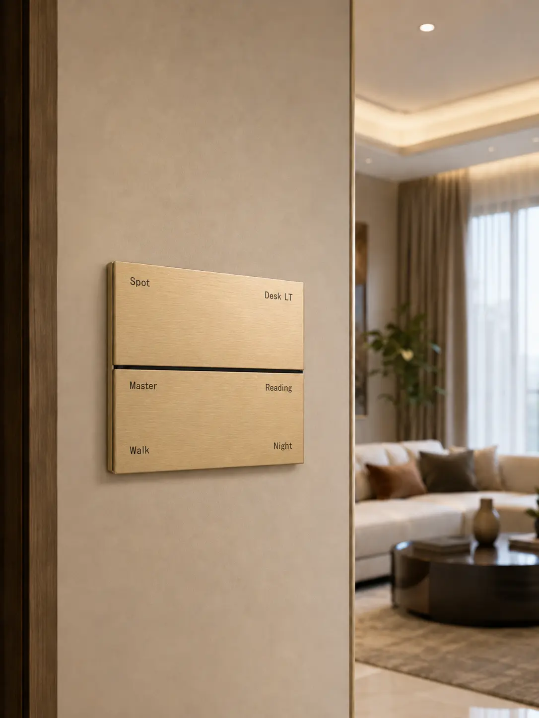
Apartments & Residences
Apply K901 wall controls to daily lighting and scene requirements in apartments and multi-residential developments, with configuration selected around the required button layout.
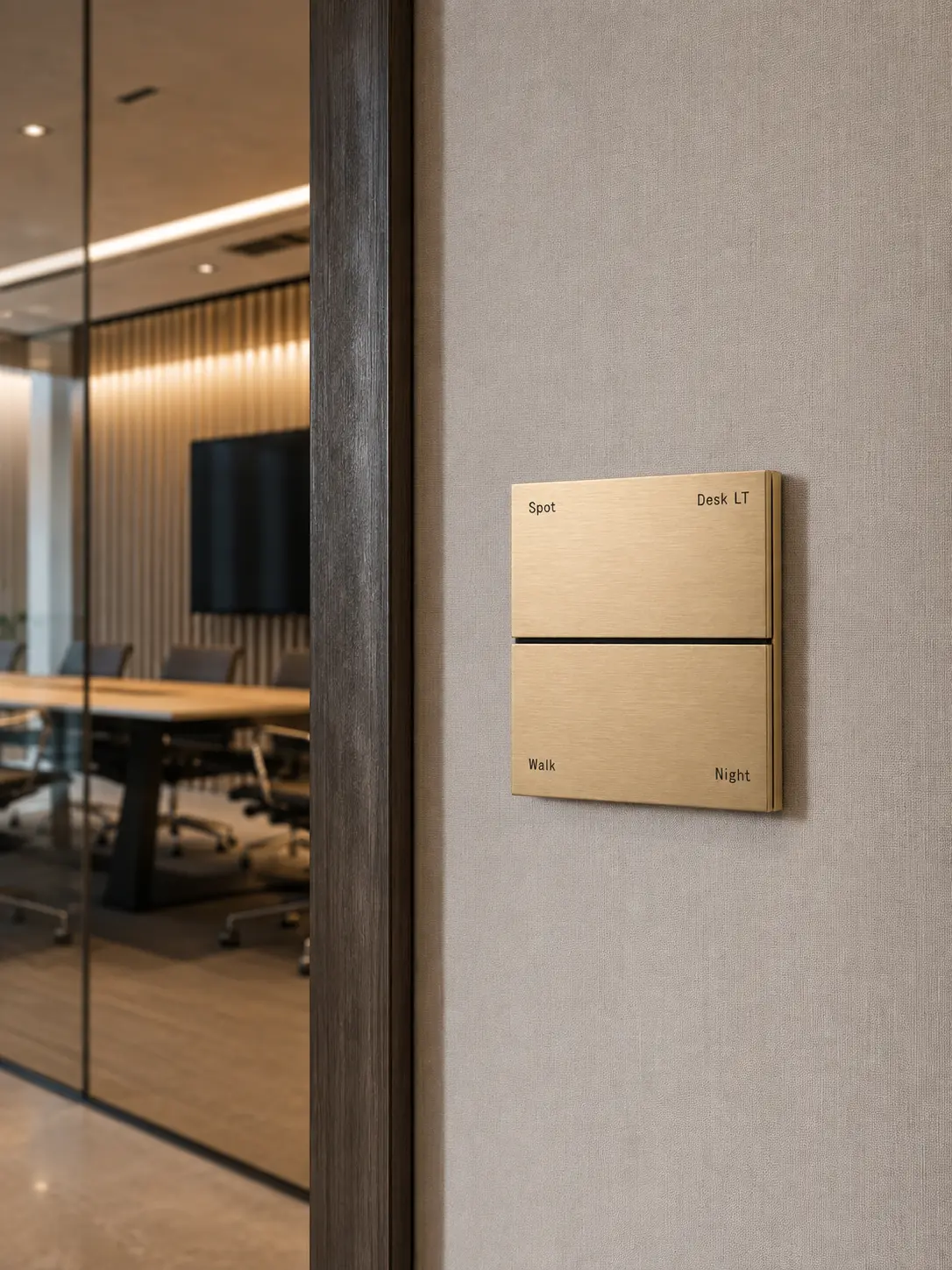
Commercial Buildings
Support offices, meeting rooms and commercial spaces with KNX TP communication, four integrated relay outputs and project-assigned button functions.
KNX Bus, Power & Relay Integration
The K901 Series combines KNX TP communication, a 12–30 V DC auxiliary supply and four integrated 16 A relay outputs for coordinated room and building control.
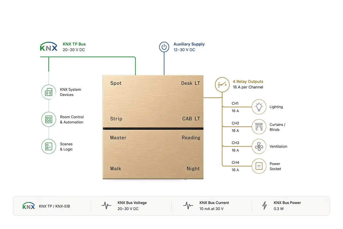
| KNX Communication | KNX TP / KNX-EIB |
|---|---|
| KNX Bus Voltage | 20–30 V DC |
| KNX Bus Current | 10 mA at 30 V |
| KNX Bus Power | 0.3 W |
| Auxiliary Supply | 12–30 V DC |
| Relay Outputs | 4 integrated channels |
| Relay Rating | 16 A per channel |
| 6-Button Auxiliary Data | 25 mA at 30 V / 0.75 W |
| 8-Button Auxiliary Data | 52 mA at 30 V / 1.56 W |
This diagram presents the functional relationship between the KNX bus, auxiliary power and integrated relay outputs. For project-specific terminal assignments and installation guidance, contact DERVIRGA technical support.
Standard Dimensions for Fast Project Installation
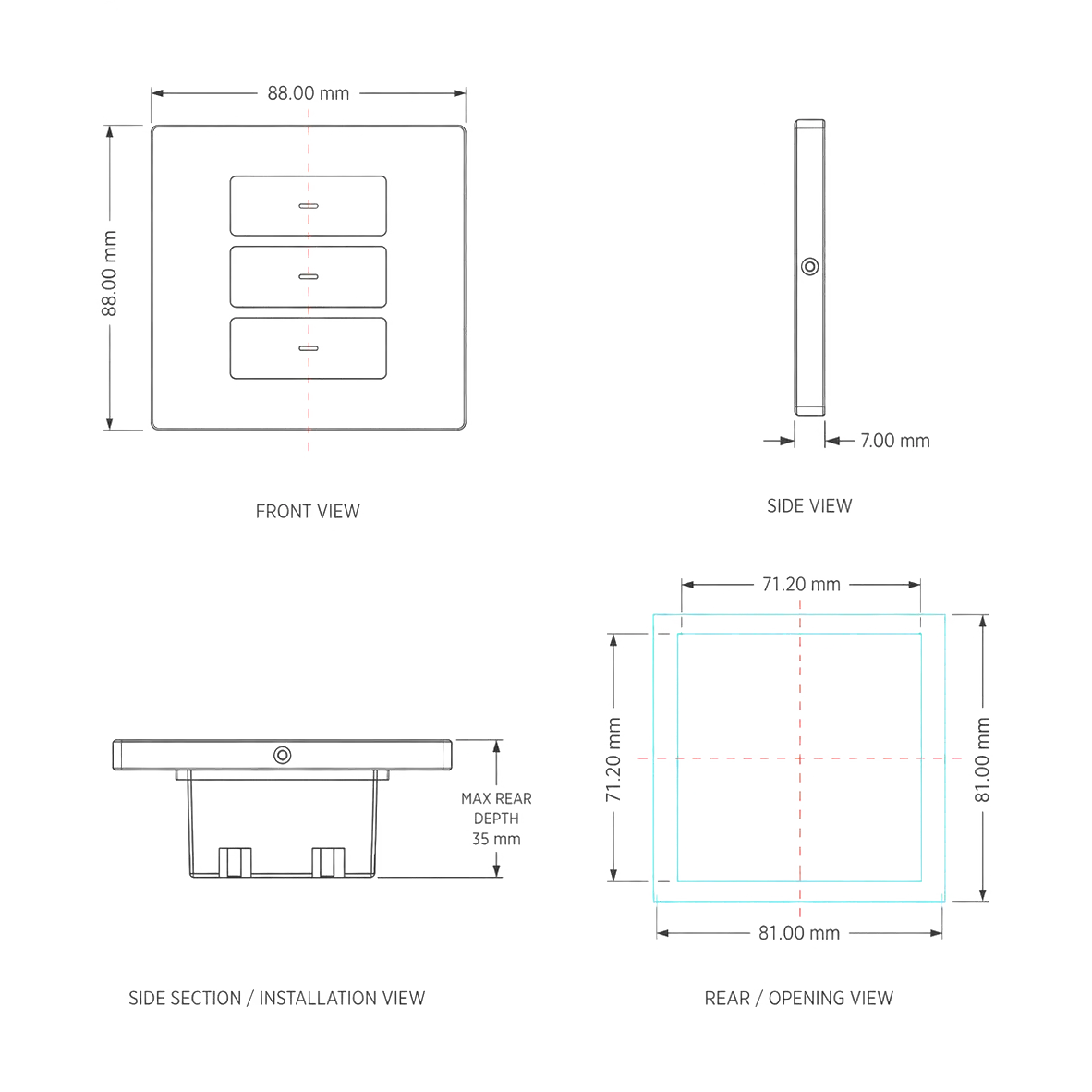
The K901 Series uses a standard 86 × 86 mm panel format with a 7 mm front panel and 35 mm rear housing, designed for installation in a standard 86-type wall back box for residential, hotel and commercial KNX projects.
Product Dimensions
Panel Size
Panel Thickness
Rear Housing Depth
Installation Process
Confirm that the standard 86-type wall back box is securely installed and provides sufficient internal space for the device and project wiring.
Connect the KNX TP bus and 12–30 V DC auxiliary supply to the designated terminals according to the K901 product wiring documentation.
Place the 35 mm rear housing into the back box and fasten the device securely while keeping the KNX bus, auxiliary power and relay wiring properly arranged.
Fit the metal front panel, complete KNX commissioning and test the assigned button functions and four relay outputs for the project configuration.
Installation, wiring and KNX commissioning must be completed by qualified professionals. Verify the 86-type back-box depth, available wiring space, auxiliary power supply and relay-load requirements before installation.
Request K901 Technical Information and Project Support
Request K901 technical information for product selection, installation, wiring and KNX project coordination. Resources are matched to the selected 4-, 6- or 8-button layout and the requirements of each project.
Need K901 Technical Assistance?
Share the required button layout, project type and integration requirements. DERVIRGA will help identify the suitable K901 configuration and coordinate the supporting technical information for your application.
4-, 6- and 8-button layout selection for project requirements
KNX TP, 12–30 V DC auxiliary power and four 16 A relay-output integration
Metal finish, icons, text and OEM/ODM project coordination
Technical Information Requests
Request K901 electrical data, button configurations, relay information, metal finishes and product-selection details.
Request mounting guidance for the 86-type wall back box, installation sequence, connection preparation and commissioning precautions.
Request model-specific KNX TP, auxiliary-power and four-channel relay-output connection information for project engineering.
Request the K901 mechanical reference covering the 86 × 86 mm panel, 7 mm front-panel thickness and 35 mm rear housing.
Contact DERVIRGA for ETS information, certification inquiries, project documents, samples and application-specific support.
Configure the K901 Series for Your Project and Brand
Configure the K901 Series for hotel, residential, commercial and OEM/ODM projects. Select the 4-, 6- or 8-button layout, coordinate the required metal surface process, and define function markings, branding and relay control assignments for the project.
Review brushed and anodized, sandblasted and anodized, or electroplated surface processes and confirm the required project appearance before sample approval and production.
Select the 4-, 6- or 8-button layout and coordinate approved function labels and icons with the room-control schedule and project application.
Coordinate approved function icons, text labels and project branding or logo marking for hotel, residential, commercial and OEM/ODM applications.
Confirm control assignments for the four integrated 16 A relay channels together with sample requirements, packaging details and the technical documents required for review.
Build Your K901 Project Configuration
Share your K901 project requirements with DERVIRGA. Our team will help coordinate the button layout, metal surface process, function markings, branding, relay assignments and project documentation for review.
Select the 4-, 6- or 8-button layout and define the required room-control functions
Confirm the surface process, required appearance, function icons, text labels and branding
Provide the project type, quantity, relay assignments, packaging, destination market and required documents
Please include the K901 button layout, project type, quantity, surface process, function marking or branding requirements, relay control needs, destination market, and whether samples or technical files are required.